CJ 20 Series
Heat shrink medium voltage joints
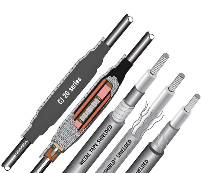
The CJ 20 series joints are single core, 5 kV to 35 kV, heat shrink joints for XLPE and EPR extruded dielectric, metal tape, wire and lead sheath shielded power cables. The CJ 20 series joints are supplied with all of the hardware required to shield and externally ground the joint without soldering. Most of the joints can be supplied with either a tube or a wraparound sleeve for the outer jacket.
Features and Benefits
- Fast, consistent installation means lower installed costs
- Installation environment: use of torch adds flexibility to cable preparation in any climate
- Heat activated seal ensures maximum protection against moisture ingress
- Wraparound jacket sleeve option (W) allows for reduced installation space
- Lightweight construction requires no additional support
- Wide cable ranges for reduced inventory requirements
- Tough abrasion resistant outer covering protects against damage from improper backfill
- Slim profile allows installation in confined areas
Standards
- IEEE 404-2000
Tests Reports
The CJ 20 series joints were design tested to IEEE404- 2000 at an independent laboratory as single core unjacketed joints. This represents the worst case condition as the joints submerged under water were not afforded the added protection of the CJ 20 series joints with tubular or wraparound jackets.
Test reports are available as follows:
- CJ820 series: HVS020079
- CJ1520 series: HVS020080
- CJ2520 series: HVS020081 and HVS020083
- CJ3520 series: HVS020082
Market/Applications
- Transit
- Water/Waste Water Treatment
- Shipboard
- Communication Power & Control
- Industrial Construction/Automation
- Civil Construction Projects
- Industrial
- Communications Cable Splice & Protection
- Petrochem/Pulp & Paper
- Commercial Construction Projects
- Mining
*Note: Joint tests to IEEE 404-2000 IEEE standards for Extruded and Laminated Dielectric Shielded Cable Joints Rated 2500 V to 500 000 Volt
Ordering
- Find the cables voltage class and conductor size(s) to be spliced. Select the kit order number that covers the conductor size range.
- Confirm the dimensional data particularly when the conductor size is at the extremes of the range. The installation space required for joints with tube jackets (CJ 820, CJ 1520, etc.) is approximately two times that of the installed joint length. This installation space can be reduced to the installed length plus six inches by adding the suffix to the end of the order number. FOR EXAMPLE a CJ 1523 needs approximately 64 in for installation. The CJ 1523W with wraparound jacket sleeve takes only 38 in of free space. CJ 2523W – CJ 3523W are not available with tube jackets. The overlap in size range allows for size transitions when splicing different cable sizes. The determining factors for selection are the dimension ranges for the primary insulation and connector dimensions, and the jacket diameter.
- A cable preparation/cleaning kit can be included with the kit by adding the suffix to the end of the order number.
| Order Number | Conductor Size Range | insulation O.D. Range | Jacket O.D. Maximum | Connector Dimensions | Nominal Kit installed Length | ||||||
| Maximum O.D. | Maximum Length | ||||||||||
| in | mm | in | mm | in | mm | in | mm | in | mm | ||
| 5 KV (90 – 110 mils) | |||||||||||
| CJ 821(W) | #8 – 2/0 AWG | 0.35 – 0.65 | 9 – 17 | 0.85 | 22 | 0.50 | 13 | 3.00 | 76 | 24.0 | 610 |
| CJ 822(W) | 3/0 – 300 kcmil | 0.55 – 0.90 | 14 – 23 | 1.20 | 29 | 0.75 | 19 | 4.25 | 108 | 26.0 | 660 |
| CJ 823(W) | 350 – 750 kcmil | 0.80 – 1.15 | 20 – 30 | 1.80 | 46 | 1.10 | 28 | 6.00 | 152 | 28.0 | 711 |
| CJ 824(W) | 1000 – 1500 kcmil | 1.00 – 1.60 | 25 – 41 | 2.30 | 58 | 1.45 | 37 | 8.00 | 203 | 30.0 | 762 |
| 8 kV (115 mils) | |||||||||||
| CJ 821(W) | #6 – #2 AWG | 0.35 – 0.65 | 9 – 17 | 0.85 | 22 | 0.50 | 13 | 3.00 | 76 | 24.0 | 610 |
| CJ 822(W) | #1 – 4/0 kcmil | 0.55 – 0.90 | 14 – 23 | 1.20 | 29 | 0.75 | 19 | 4.25 | 108 | 26.0 | 660 |
| CJ 823(W) | 250 – 350 kcmil | 0.80 – 1.25 | 20 – 32 | 1.80 | 46 | 1.10 | 28 | 6.00 | 152 | 28.0 | 711 |
| CJ 824(W) | 500 – 750 kcmil | 1.00 – 1.60 | 25 – 41 | 2.30 | 58 | 1.45 | 37 | 8.00 | 203 | 30.0 | 762 |
| CJ 825(W) | 750 – 1000 kcmil | 1.30 – 2.10 | 33 – 53 | 2.50 | 64 | 1.85 | 47 | 8.00 | 203 | 30.0 | 762 |
| 15 kV (175 – 220 mils) | |||||||||||
| CJ 1521(W) | #4 – 4/0 AWG | 0.60 – 1.05 | 15 – 27 | 1.25 | 32 | 1.05 | 26 | 4.25 | 108 | 28.0 | 711 |
| CJ 1522(W) | 4/0 – 500 kcmil | 0.80 – 1.25 | 20 – 32 | 1.50 | 38 | 1.25 | 32 | 5.50 | 140 | 30.0 | 762 |
| CJ 1523(W) | 400 – 750 kcmil | 1.05 – 1.60 | 27 – 41 | 1.85 | 47 | 1.75 | 44 | 8.00 | 203 | 32.0 | 813 |
| CJ 1524(W) | 750 – 1750 kcmil | 1.30 – 2.15 | 33 – 55 | 2.45 | 62 | 2.15 | 55 | 8.00 | 203 | 32.0 | 813 |
| 25 – 28 kV (260 – 280 mils) | |||||||||||
| CJ 2521(W) | #1 – 250 kcmil | 0.80 – 1.25 | 20 – 32 | 1.50 | 38 | 1.10 | 28 | 4.00 | 102 | 30.0 | 762 |
| CJ 2522(W) | 4/0 – 500 kcmil | 1.05 – 1.55 | 27 – 39 | 1.95 | 50 | 1.30 | 33 | 6.00 | 152 | 34.0 | 864 |
| CJ 2523 W | 600 – 1000 kcmil | 1.40 – 1.85 | 33 – 47 | 2.40 | 61 | 1.85 | 47 | 8.00 | 203 | 36.0 | 915 |
| 35 kV (345 mils) | |||||||||||
| CJ 3521 W | 1/0 – 250 kcmil | 0.95 – 1.35 | 24 – 34 | 1.55 | 39 | 1.00 | 25 | 5.00 | 127 | 39.0 | 991 |
| CJ 3522 W | 250 – 600 kcmil | 1.30 – 1.75 | 33 – 44 | 2.10 | 53 | 1.50 | 38 | 8.00 | 203 | 42.0 | 1067 |
| CJ 3523 W | 600 – 1000 kcmil | 1.55 – 2.15 | 39 – 55 | 2.80 | 71 | 1.85 | 47 | 10.00 | 254 | 46.0 | 1168 |


