FCFW
Heavy wall crosslinked polyolefin
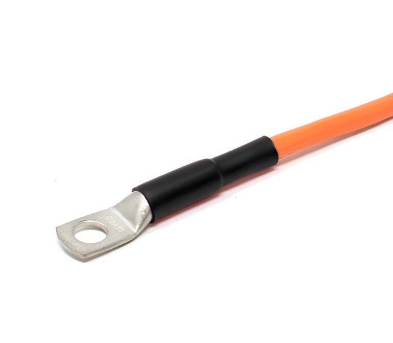
Heavy wall heat shrink tubing insulates and protects electrical splices and terminations where maximum flame retardancy and exceptional insulating and sealing characteristics are required.
Features and Benefits
- Flame retardant
- UV resistant
- High impact and abrasion resistance – capable of withstanding severe mechanical abuse of U.R.D., submersible and direct burial installations
- Optional thermoplastic adhesive liner provides complete environmental protection and insulation
- Rated for up to 2 kV
- Shrink ratio: 3:1
- Continuous operating temperature: -55°C to 110°C
- Shrink temperature: 120°C min.
Standards
- UL 486D – UL file # E132914
- CSA C22.2 No. 198.2
- IEC 60684-3-247
- ICEA S-19-8 and NEMA insulation thickness requirements
- QPL AS23053/15 Class 1 (Select sizes only, adhesive-lined only,
black color only - Flame-retardant in accordance with ASTM D2671
Typical Applications
Insulation of low voltage cables, flame retardant systems
Market/Applications
- OEM
- Power Distribution
- Power Distribution – LV
- Industrial
- Utility
- Mining
Ordering
Select a dimension which will shrink snugly over the application to be covered. If recovery is restricted the resulting wall thickness will be less than specified.
- Select Options:
- Color: Black (BK) or red (RD)
- Printing: Printed or unprinted
- Adhesive Lining: Lined (D) or unlined (U)
- Please specify the product name, order number and options you require
- Example: FCFW, 1500, U, black, unprinted, 1.22 m length
Please contact your Customer Service Representative for information on custom colors, sizes, lengths and material data sheet.
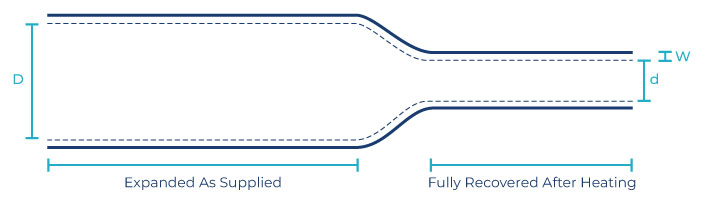
| Order Number | Expanded | Recovered | Application Range for General Use | 600/1000 V Single Conductor Size | Lengths | ||||||
| Internal Diameter (min) D | Internal Diameter (max) d | Wall Thickness (nom) W | |||||||||
| mm | in | mm | in | mm | in | mm | in | awg/mcm | m | in | |
| 0350** | 8.6 | 0.34 | 2.5 | 0.12 | 1.8 | 0.07 | 3.5 – 8 | .15 – .3 | #14 – #10 | 1.2 | 48 |
| 0400** | 10.2 | 0.40 | 3.3 | 0.13 | 1.8 | 0.07 | 3.5 – 9 | .15 – .35 | #10 – #8 | 1.2 | 48 |
| 0500** | 13.0 | 0.51 | 4.1 | 0.16 | 2.4 | 0.08 | 4.5 – 11 | .2 – .45 | #8 – #6 | 1.2 | 48 |
| 0750 ** | 19.1 | 0.75 | 6.1 | 0.22 | 2.5 | 0.09 | 6.5 – 16.5 | .25 – .65 | #6 – #2 | 1.2 | 48 |
| 1100 | 27.9 | 1.10 | 8.9 | 0.35 | 3.0 | 0.12 | 10 – 24 | .4 – .95 | #1 – 3/0 | 1.2 | 48 |
| 1500 | 38.1 | 1.50 | 11.9 | 0.47 | 4.1 | 0.16 | 13 – 35 | .5 – 1.4 | 2/0 – 350 | 1.2 | 48 |
| 2000 | 50.8 | 2.00 | 16.0 | 0.63 | 4.1 | 0.16 | 17.5 – 44 | .7 – 1.75 | 250 – 500 | 1.2 | 48 |
| 2700 | 68.1 | 2.70 | 22.1 | 0.87 | 4.1 | 0.16 | 24 – 59 | .95 – 2.3 | 600 – 1000 | 1.2 | 48 |
| 3500* | 89.9 | 3.54 | 30.0 | 1.18 | 4.1 | 0.16 | 33 – 80 | 1.3 – 3.1 | 800 – 1250 | 1.2 | 48 |
| 4700* | 119.9 | 4.72 | 39.9 | 1.57 | 4.2 | 0.17 | 44 – 104 | 1.75 – 4.1 | 1500 – 2500 | 1.2 | 48
|
* FCFW 3500 and FCFW 4700 are not UL, or CSA listed.
** QPL AS23053/15 Class 1, adhesive-lined only, black color only