CBTH – EMEA
Heavy wall crosslinked Polyolefin bus bar tubing
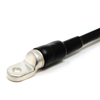
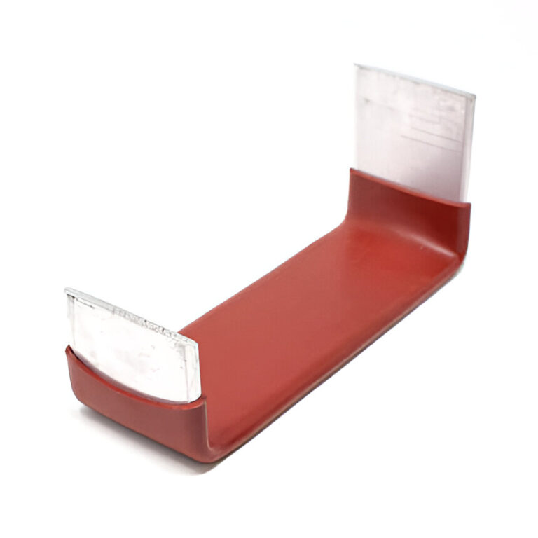
Heavy wall anti-track heat shrinkable tubing specifically designed for insulating medium voltage bus bars.
Features and Benefits
- Halogen free
- Reduces bus bar clearance requirements
- Protects against accidental flashover
- Anti-track
- CBTH heavy wall tubing rated to 36 kV
- Shrink ratio: 3:1
- Continuous operating temperature: -40°C to 125°C
- Shrink temperature: 120°C
Standards
- ANSI C37.20.2
- ANSI C37.20.3
- UL file # E205844
Typical Applications
Insulation of medium voltage bus bars in switchgear equipment, transformers and generators
Market/Applications
- OEM
- Power Distribution
- Industrial
- Power Distribution – MV
- Utility
Ordering
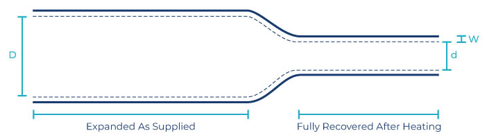
Select a dimension which will shrink snugly over the component to be covered. If recovery is restricted the resultant wall thickness will be less than specified.
- Select options:
- Color: Red (RD)
- Please specify the product name, order number and options you require
- Order example: CBTH 2700, 68.0/22.1, red
Please contact your Customer Service Representative for information on custom colors, sizes, lengths and material data sheet.
| Order Number | Expanded | Recovered | Delivery Units | |||||
| Internal Diameter (Min) D |
Internal Diameter (Max) d |
Total Wall Thickness (Nom) W |
Lengths | |||||
| mm | in | mm | in | mm | in | m | ft | |
| 1100 | 27.9 | 1.098 | 8.9 | 0.350 | 3.90 | 0.154 | 15.24 | 50 |
| 2000 | 50.8 | 2.000 | 16.0 | 0.630 | 4.10 | 0.161 | 15.24 | 50 |
| 2700 | 68.0 | 2.677 | 22.1 | 0.870 | 4.10 | 0.161 | 15.24 | 50 |
| 3500 | 89.9 | 3.539 | 29.9 | 1.177 | 4.20 | 0.165 | 15.24 | 50 |
| 4700 | 119.9 | 4.720 | 39.9 | 1.571 | 4.20 | 0.165 | 15.24 | 50 |
| 6600 | 167.6 | 6.598 | 65.0 | 2.559 | 4.20 | 0.165 | 15.24 | 50 |
| Order Number | Application Ranges | |||||
| Rectangular Bus Bars | Round Bus Bars | |||||
| Min | Max | Min – Max | ||||
| mm | in | mm | in | mm | in | |
| 1100 | 9.5 x 6.4 | 0.374 x 0.252 | 12.7 x 15.9 | 0.500 x 0.626 | 10.6 – 17.7 | 0.417 – 0.697 |
| 2000 | 25.4 x 6.4 | 1.000 x 0.252 | 34.9 x 15.9 | 1.374 x 0.626 | 19.3 – 33.0 | 0.760 – 1.299 |
| 2700 | 34.9 x 6.4 | 1.374 x 0.252 | 40.8 x 15.9 | 1.606 x 0.626 | 26.1 – 43.1 | 1.028 – 1.697 |
| 3500 | 50.8 x 6.4 | 2.000 x 0.252 | 76.2 x 15.9 | 3.000 x 0.626 | 35.8 – 58.4 | 1.409 – 2.299 |
| 4700 | 69.8 x 6.4 | 2.748 x 0.252 | 111.1 x 15.9 | 4.374 x 0.626 | 47.7 – 81.2 | 1.878 – 3.197 |
| 6600 | 107.9 x 6.4 | 4.248 x 0.252 | 177.8 x 15.9 | 7.000 x 0.626 | 69.5 – 124.4 | 2.736 – 4.898 |
Application ranges noted above selected to obtain minimum insulation thickness required to meet ANSI C37.20.2 withstands requirements at bus bar spacing noted below. These spacings were determined from a limited number of test configurations. Due to the wide variety of bus bar configurations, these spacings should not be employed without actual testing by the user.
Clearances with Insulation
| System Voltage | BIL kV | CBTM Medium Wall Tubing | |||
| P to P | P to G | ||||
| mm | in | mm | in | ||
| 15 kV | 95.0 | 55.0 | 2.165 | 66.0 | 2.598 |
| 25 kV | 125.0 | 71.0 | 2.795 | 101.0 | 3.976 |
| 36 kV | 150.0 | 142.0 | 5.591 | 190.0 | 7.480 |
P to P: Phase to Phase orientation
P to G: Phase to Ground orientation
Spacing based on metal to metal dimension prior to insulation Spacing based on insulation wall thickness per application range of above table.